Monday 16 January 2012

Question Of The Day(AIEEE)

A particle moves along the xaxis as x = u(t-1)2 + a(t-3)3

[a] initial velocity of the particle is u

[b] the acceleration of the particle is a

[c] the acceleration of the particle is 2a

[d] the particle is at the origin at time t=3 seconds

Question Of The Day(CET)

A straight wire of diameter 0.5mm carrying a current of 1A is replaced by another wire of radius 1mm diameter and carrying the same current. The strength of the magnetic field far away is

[a] twice the earlier value

[b] one half of the earlier value

[c] one quarter of the earlier value

[d] same as the earlier value

Saturday 14 January 2012

Electric Current Basics

Electric Current Basics

Electrostatics Basics

ElectroStatics Basics

Question Of The Day(AIEEE)

Find the angle of minimum deviation for an equilateral prism made of a material of refractive index 1.732. What is the angle of incidence for this deviation ?

a)60
b)0
c)30
d)90

Question Of The Day(CET)

If the resistivity of potentiometer wire be ρ and area of cross section be A, then what will be the potential gradient along the wire?

[a] Iρ/A [b]I/ρA

[c] IA/ρ [d] Iaρ

Friday 13 January 2012

Magnetic Effect Of Electric Current Notes

Magnetic Effect Of Electric Current

Thursday 12 January 2012

Question Of The Day

IN NPN transistor, the collector current is 24mA. If 80% of the electrons reach collector, the base current in mA is
             [a] 36                                       [b] 26
             [c] 16                                       [d]6

Question Of The Day

Within depletion region of the pn junction diode
             [a] p side is positive and n side is negative
             [b] p side is negative and n side is +ive
             [c] both sides are either positive or negative
             [d] both sides are neutral

Question Of The Day

Two batteries of different emfs are connected in series with each other and with external load resistance. The current is 3A. when the polarity of one of the batteries is reversed the current is 1A. the ratio of emf’s of the two batteries is
        [a] 2.5                     [b] 2
        [c] 1.5                     [d] 1

Question Of The Day

The magnitude of earth’s magnetic field at the North pole is B. a horizontal conductor of length l moves with velocity v. the direction of v is perpendicular to the conductor. The induced emf is
        [a] zero, if v is vertical          [b] B0lv, if v is vertical
        [c] zero, if v is horizontal       [d]B0lv is v is horizontal

Question Of The Day,

A vertical conducting ring of radius R falls vertically in a horizontal magnetic field of magnitude B. the direction of B is perpendicular to the plane of the ring. When the speed of the ring is v,  
        [a] no current flows in the ring
        [b] A and D are at the same potential.
        [c] C and E are at the same potential
        [d] the potential difference between A and D is 2Brv, with D at higher potential.
   

Theory Of Relativity(Animation)

A spaceship is flying a distance of 5 light hours, for example from Earth to the dwarf planet Pluto. The speed can be regulated with the upper buttons. The applet demonstrates that the clock in the spaceship goes more slowly than the two clocks of the system in which Earth and Pluto are motionless.


For Animation CLICK HERE

Diffraction of Light by a Single Slit(Animation)

Interference of Light at a Double Slit(Animation)

In this Animation you can vary the wavelength,spacing between the slits,angle and you can observe the effect of this on width of fringe and intensity of fringe,


For Animation CLICK HERE

Image Formation by Converging Lenses(Animation)

Reflection and Refraction of Light Waves(Animation)

This applet is a sort of tutorial which explains the reflection and the refraction of waves by the principle of Huygens. Explanations of each of the steps are provided in the text box. Whenever a step is finished, press the "Next step" button! You can stop and continue the simulation by using the "Pause / Resume" button. The three text fields make it possible to vary the index of refraction of both media and the angle of incidence. The medium with the smaller index of refraction (the bigger phase velocity) is painted yellow, the other blue.


For Animation CLICK HERE

Refraction of Light(Animation)

A ray of light coming from the top left strikes the boundary surface of two media. (It is possible to choose the substances in both lists.) The medium which has the bigger index of refraction is painted blue, the other yellow. You can vary the incident ray with pressed mouse button. The applet will show the reflected and the refracted ray and calculate the corresponding angles:

Angle of incidence(black)
Angle of reflection(blue)
Angle of refraction(red)

For Animation CLCK HERE

of a Straight Current-Carrying Wire(Animation)

An electric current produces a magnetic field. This applet simulates an experiment concerning the magnetic field of a straight current-carrying wire. A large current passes through a vertical wire. You can reverse the direction of this current by using the red button. The signs at the ends of the wire symbolize the poles of the connected battery. The conventional direction of current is given by the red arrow. Note that the motion of the electrons (green dots) is opposite to the conventional direction!
A compass needle which can be moved (by dragging the mouse with pressed mouse button) shows the direction of the magnetic field (blue) at a given position. North and south pole of the compass needle are painted with red respectively green colour. The influence of the earth's magnetic field is neglected in this simulation.


For Animation CLICK HERE

Lorentz Force(Animation)

This Java applet demonstrates the Lorentz force, exerted on a current-carrying conductor swing in the magnetic field of a horseshoe magnet.
You can switch on (off) the current by using the upper button ("On / Off"). The other two buttons ("Reverse current" and "Turn magnet") make it possible to change the direction of the current respectively of the magnetic field. If the corresponding checkboxes are selected, the applet will indicate the conventional direction of current (red arrows), the magnetic field lines (blue) and the Lorentz force (black arrow).


For Animation CLICK HERE

Direct Current Electrical Motor(Animation)

This Java applet shows a direct current electrical motor which is reduced to the most important parts for clarity. Instead of an armature with many windings and iron nucleus there is only a single rectangular conductor loop; the axis the loop rotates on is omitted.
The red arrows indicate the conventional direction of current (from plus to minus). You can recognize the magnetic field lines (directed from the red painted north pole to the green painted south pole) by the blue color. The black arrows represent the Lorentz force which is exerted on a current-carrying conductor in the magnetic field.
The mentioned Lorentz force is orthogonal to the direction of current and to the magnetic field lines. The orientation of this force results from the well-known three finger rule (for the right hand!)


For Animation CLICK HERE

Generator(Animation)

This Java applet simulates a generator which is reduced to the most important parts for clarity. Instead of an armature with many windings and iron nucleus there is only a single rectangular conductor loop; the axis the loop rotates on is omitted.
The radio buttons in the top right corner allow you to choose an AC generator (without commutator), or a DC generator (with commutator). You can change the direction of rotation by using the corresponding button. The sliding control makes it possible to vary the rotational speed. You can stop and continue the simulation with the button "Pause / Resume". This, however, does not mean a real stop of the movement, for in this case the induced voltage would be reduced to zero.
Two black arrows mark the momentary direction of movement. You can recognize the magnetic field lines (directed from the red painted north pole to the green painted south pole) by the blue color. The red arrows represent the direction of the induced current (conventional direction of current).


For Animation CLICK HERE

Simple AC Circuits(Animation)

Java applet shows a simple circuit consisting of an alternating voltage source and, depending on the selected radio button, a resistor (without inductivity), a capacitor or an ideal coil (without resistance). In addition there are meters for the voltage U (blue) and the amperage I (red).
Below the drawing of the circuit you see on the left a phasor diagram; it is possible to read the momentary oscillation phases from the position of the two phasors (voltage blue, amperage red). The projection of a phasor onto the vertical axis corresponds to the momentary value of U respectively I. On the bottom right the dependence of voltage and amperage on the time is illustrated in a diagram.
The "Reset" button brings the circuit to its initial state. You can start or stop and continue the simulation with the other button. If you choose the option "Slow motion", the movement will be five times slower.
It is possible to vary the preselected values of frequency, maximal voltage and resistance respectively capacity or inductivity. The program will indicate the new value of the maximal amperage


For Animation CLICK HERE

Potentiometer(Animation)

In this animation you can change position of the sliding contact.You can observe the changes in output voltages and current.


For Animation CLICK HERE

Electromagnetic Oscillating Circuit(Animation)

This simulation deals with an electromagnetic oscillating circuit, consisting of a capacitor (center) and an inductor (i.e. a coil, on the right). As soon as you have pressed the "Reset" button, the plates of the capacitor will be charged, namely the upper plate positively and the lower plate negatively. After clicking on the "Start" button with the mouse, the switch will be brought to its other position so that the oscillation will begin. The same button makes it possible to interrupt respectively resume the simulation. The animation will be 10 or 100 times slower than the real oscillation, depending on the selected radio button. You can vary the values of the capacity (from 100 μF to 1000 μF), the coil's inductivity (from 1 H to 10 H) and resistance (from 0 Ω to 1000 Ω) and the voltage of the battery by using the four text fields.
The electric field of the capacitor (red) and the magnetic field of the inductor (blue) are indicated by field lines in the circuit diagram. The density of these field lines shows the strength of the corresponding field. In addition, you can see the charge signs of the two capacitor plates and arrows for the (conventional) current direction.
At the left bottom a digital clock indicates the time since the begin of the oscillation; under there you can read the oscillation period. At the right bottom one of two diagrams is to be seen, depending on the selected radio button in the lower part of the control panel:
1. A diagram which shows as voltage U (blue) and amperage I (red) vary in time.
2. A bar graph which describes the transformations of energy.


For Animation CLICK HERE

Wednesday 11 January 2012

Electromagnetic Wave(Animation)

This animation shows an electromagnetic wave, namely a plane polarized wave, which propagates in positive x direction. The vectors of the electric field (red) are parallel to the y axis, the vectors of the magnetic field (blue) are parallel to the z axis.

For Animation CLICK HERE

Combinations of Resistors, Inductors and Capacitors(Animation)


This animation will give you the idea about  series and parallel connection of resistors and inductors and capacitors.Rightside you can see so many buttons like replace parallel series and all.click on that and observe the changes.

For Animation CLICK HERE

Interference of two Circular or Spherical Waves

This Java applet shows the interference of two circular respectively spherical waves (e.g. of water or sound waves). The waves spread out from two sources oscillating with the same phase. For the interference of the waves the principle is valid that the elongations are added, considering their signs.
You can observe the following two extreme cases:
At those points, where the difference Δs of the path lengths (the difference of the distances from the two sources) is an integer multiple of the wavelength λ, the waves arrive with the same phase: This means that maxima (black circles) respectively minima (gray circles) always arrive at the same time, so that the interference is constructive (maximal amplitude). Points with this property are situated on the red marked curves respectively surfaces.
At those points, where the difference Δs of the path lengths is an odd half-integer multiple of the wavelength λ, there are opposite conditions: At those points which are situated on the blue painted curves respectively surfaces a maximum of one wave always arrives simultaneously with a minimum of the other one, so that the resulting wave is diminished (destructive interference, minimal amplitude).
The button "Pause / Resume" of the applet makes it possible to stop or continue the simulation. If you choose the option "Slow motion", the animation will be five times slower. You can vary the distance of the two sources and the wavelength by using the corresponding text fields (Don't forget to press the "Enter" key!). At the bottom the program indicates the difference Δs of the path lengths (see above) for the violet coloured point. You can move this point with pressed mouse button.


For Animation CLICK HERE

Beats(Animation)

Simple Pendulum(Animation)


This Java applet demonstrates the variation of elongation, velocity, tangential acceleration, force and energy during the oscillation of a pendulum (assumed with no friction).
The "Reset" button brings the body of pendulum to its initial position. You can start or stop and continue the simulation with the other button. If you choose the option "Slow motion", the movement will be ten times slower. The length of the pendulum, the gravitational acceleration, the mass and the amplitude of the oscillation can be changed within certain limits. In order to select another physical size you have to click on the appropriate one of the five radio buttons.
The insignificant dependence of the oscillation period upon the amplitude was neglected in the calculations.


For Animation CLICK HERE

Uniform Circular Motion(Animation)

Circular motion plays an important role in nature and technology. So, the planets move on (approximately) circular orbits around the sun. Other examples are the rotating armature of an electric motor or the crankshaft of a gasoline engine.
This Java applet simulates such a circular motion and demonstrates how position, velocity, acceleration and acting force vary in time. The "Reset" button brings the rotating body in its initial position. You can start or stop and continue the simulation with the other button. If you choose the option "Slow motion", the movement will be ten times slower. You can adjust radius, period and mass by using the corresponding input fields. The radio buttons give the possibility to select one of four physical sizes


For Animation CLICK HERE

Elastic and Inelastic Collision(Animation)


This Java applet deals with the extreme cases of a collision process illustrated by two wagons: For an elastic collision it is characteristic that the sum of the kinetic energies of the involved bodies is constant. After a perfectly inelastic collision, however, both bodies have the same velocity; the sum of their kinetic energies is reduced, compared with the initial value, because a part of it has changed into internal energy (warming up).
The total momentum of the involved bodies is conserved, regardless whether the collision is elastic or inelastic. The movement of the common center of gravity (indicated by a yellow dot) is not influenced by the collision process.
You can choose the simulation of an elastic or an inelastic collision by using the appropriate radio button on the top right. The "Reset" button brings the wagons to their initial positions; the animation is started by a mouse click on the "Start" button. If you select the option "Slow motion", the movement will be ten times slower.
You can write the values of mass and initial velocity into the textfields. Positive (negative) values of velocity mean a motion to the right (left) side. Extreme inputs are automatically changed.
Dependent on the selected radio button (on the bottom right), the applet will illustrate the velocities, the momenta or the kinetic energies of the wagons


For Animation CLICK HERE


Projectile Motion(Animation)

This Java applet shows the motion of a projectile.
The "Reset" button brings the projectile to its initial position. You can start or stop and continue the simulation with the other button. If you choose the option "Slow motion", the movement will be ten times slower. You can vary (within certain limits) the values of initial height, initial speed, angle of inclination, mass and gravitational acceleration. The radio buttons give the possibility to select one of five physical sizes.
The effect of air resistance is neglected.


For Animation Click Here

Resolution of a Force into Components(Animation)

When solving physics problems, it is often helpful to replace one force by a combination of two forces with given directions. Of course, these two forces must be equivalent to the given one. This means that their vector sum must agree with the given force. If this condition is fulfilled, we say that the force has been resolved into components.
A simple geometrical construction provides the magnitudes of the components: We can draw two lines from the end of the given force vector parallel to the given directions. In this way, we get the so-called parallelogram of forces. The magnitudes of the components now can be read off from the sides of this parallelogram.
You can modify the given force and the given directions by using the textfields or by dragging the mouse (with pressed mouse button). If you click on the upper one of the two buttons ("Find out components"), the program will carry out the explained construction, and the magnitudes of the two components will be written on the control panel. The construction can be cleared by a mouse click on the lower button.


For Animation CLICK HERE

Resultant of Forces(Animation)

This applet deals with forces exerted on a body (assumed as point-sized). You can vary the number of single forces by using the choice box at the ride side. It is possible to change the sizes and directions of these forces (blue arrows) by dragging the arrowheads to the intended positions with pressed mouse button.
If you want to know the total force which is exerted on the body, you have to carry out a vector addition. As soon as you have clicked on the button "Find out resultant" the program will show you the necessary parallel translations of the force arrows and then draw the arrow of the resultant (red). The construction can be cleared by a mouse click on the lower button.


For Animation CLICK HERE

Equilibrium of Three Forces

A simple experiment concerning the equilibrium of three forces is simulated here: Weights are suspended from three tied cords. Two of the cords run over frictionless pulleys. The three forces acting on the knot (coloured arrows) are in equilibrium.
You can write forces from 1 N to 10 N into the text fields (don't forget to press the "Enter" key!). Notice that each force must be smaller than the sum of the other two forces! It is possible to vary the positions of the two pulleys by dragging the mouse. The parallelogram of the forces which are directed to the top left and right (red respectively blue) will be drawn if you select the corresponding option. At the bottom right you can read the angles of these two forces with respect to the vertical.


For Animation CLICK HERE

Motion with Constant Acceleration (Animation)

This Java applet shows a car moving with constant acceleration. The green control panel contains text fields where you can vary the values of initial position, initital velocity and acceleration (don't forget to press the "Enter" key!). By using the buttons at the top right you can bring back the car to its initial position or stop and resume the simulation. If you choose the option "Slow motion", the movement will be ten times slower.
Three digital clocks indicate the time elapsed since the start. As soon as the car has reached the green respectively red light barrier with its front bumper, the corresponding clock will stop. Both light barriers are adjustable by dragging the mouse with pressed mouse button.
Three diagrams illustrate the motion of the vehicle:
  • Position x versus time t
  • Velocity v versus time t
  • Acceleration a versus time t


For Animation CLICK HERE

Wednesday 4 January 2012

Question of the day


The length of a simple pendulum executing simple harmonic motion is increased by 21%. The percentage increase in the time period of the pendulum of increased length is
            (A) 11%                                                           (B) 21%
            (C) 42%                                                           (D) 10%


Path of a Positively Charged Spinning Object

This animation will give you the idea about path followed by a positively charged spinning object in magnetic field.
For animation Click here

The Electric and Magnetic Field generated by an Oscillating Charge(ANIMATION)


The animation will give you the idea about The Electric and Magnetic Field generated by an Oscillating Charge..From the animation it will be more clear  how the electric field and magnetic field are perpendicular to each other.And how exactly they are perpendicular to direction of propagation also.
Watch this Its really good.
Requirements -Flash player


For Animation Click Here

Sunday 1 January 2012

WHEATSTONE BRIDGE


WHEATSTONE BRIDGE
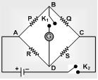
Wheatstone bridge is an arrangement of four resistances which can be used to measure one of them in terms of rest. Here arms AB and BC are called ratio arm and arms AC and BD are called conjugate arms.
Wheatstone Bridge
Balanced Wheatstone bridge: The bridge is said to be balanced when deflection in galvanometer is zero i.e. no current flows through the galvanometer or in other words VB = VD. In the balanced condition P/Q = R/S, on mutually changing the position of cell and galvanometer this condition will not change.
Unbalanced Wheatstone bridge: If the bridge is not balanced current will flow from D to B if VD > VB i.e. (VA – VD) < (VA – VB) which gives PS > RQ.
Applications of Wheatstone bridge: Meter bridge, post office box and Carey Foster bridge are instruments based on the principle of Wheatstone bridge and are used to measure unknown resistance.
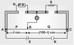
METER BRIDGE: In case of Meter Bridge, the resistance wire AC is 100 cm long. Varying the position of tapping point B, bridge is balanced. If in balanced position of bridge AB = l,
BC = (100 – l)
Meter Bridge
So that .Q/P = (100–l)/l
Also P/Q = R/S ⇒ S = (100–l)/l R
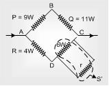
Solved example 1: In Wheatstone bridge P = 9 ohm, Q = 11 ohm, R = 4 ohm and S = 6 ohm. How much resistance must be put in parallel to the resistance S to balance the bridge
(A) 24 ohm      (B) 44/9 ohm          (C) 26.4 ohm         (D) 18.7 ohm
Solution: (C) (For balancing bridge)
⇒ S' = 4×11/9 = 44/9 ⇒ 1/S' = 1/r + 1/6
⇒ 9/44 – 1/6 = 1/r ⇒ r = 132/5 = 26.4 Ω
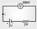
Solved example 2: A voltmeter having a resistance of 998 ohms is connected to a cell of emf 2 volt and internal resistance 2 ohm. The error in the measurement of emf will be
(A) 4 ×10⁻¹ volt                                  (B) 2 ×10⁻³ volt
(C) 4 ×10⁻³ volt                                  (D) 2 ×10⁻¹ volt
Solution: (C) Error in measurement = Actual value – Measured value
Actual value = 2A
i = 2/998+2 = 1/500 A
Since E = V + ir = ⇒ V = E – ir = 2 – 1/500 × 2 = 998/500 V
Measured value = 998/500 V ⇒ Error = 2 – 998/500 = 4 × 10⁻³ volt.
Potentiometer
Potentiometer is a device mainly used to measure emf of a given cell and to compare emf's of cells. It is also used to measure internal resistance of a given cell.
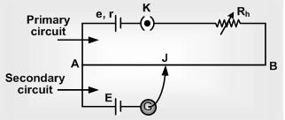
Circuit diagram: Potentiometer consists of a long resistive wire AB of length L (about 6 m to 10 m long) made up of mangnine or constantan and a battery of known voltage e and internal resistance r called supplier battery or driver cell. Connection of these two forms primary circuit.
One terminal of another cell (whose emf E is to be measured) is connected at one end of the main circuit and the other terminal at any point on the resistive wire through a galvanometer G. This forms the secondary circuit. Other details are as follows
Circuit diagram
J = Jockey
K = Key
R = Resistance of potentiometer wire,
r = Specific resistance of potentiometer wire.
Rh = Variable resistance which controls the current through the wire AB
(i) The specific resistance (r) of potentiometer wire must be high but its temperature coefficient of resistance (a) must be low.
(ii) All higher potential points (terminals) of primary and secondary circuits must be connected together at point A and all lower potential points must be connected to point B or jockey.
(iii) The value of known potential difference must be greater than the value of unknown potential difference to be measured.
(iv) The potential gradient must remain constant. For this the current in the primary circuit must remain constant and the jockey must not be slided in contact with the wire.
(v) The diameter of potentiometer wire must be uniform everywhere.
Potential gradient (x): Potential difference (or fall in potential) per unit length of wire is called potential gradient i.e. x = V/L volt/m where V = iR = (e/R+Rn+r)R.
So x = V/L = iR/L = ip/A = e/(R+Rh+r) . R/L
(i) Potential gradient directly depends upon
(a) The resistance per unit length (R/L) of potentiometer wire.
(b) The radius of potentiometer wire (i.e. Area of cross-section)
(c) The specific resistance of the material of potentiometer wire (i.e. r)
(d) The current flowing through potentiometer wire (i)
(ii) Potential gradient indirectly depends upon
(a) The emf of battery in the primary circuit (i.e. e)
(b) The resistance of rheostat in the primary circuit (i.e. Rh)
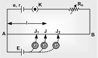
Working: Suppose jockey is made to touch a point J on wire then potential difference between A and J will be V = xl
At this length (l) two potential difference are obtained
(i) V due to battery e and
(ii) E due to unknown cell
If V > E then current will flow in galvanometer circuit in one direction 
If V < E then current will flow in galvanometer circuit in opposite direction 
If V = E then no current will flow in galvanometer circuit this condition to known as null deflection position, length l is known as balancing length.
In balanced condition E = xl
or E = xl = V/L l = iR/L l = (e/R+Rh+r) × R/L × l
If V is constant then L ∝ l ⇒ x1/x2 = L1L2 = l1/l2
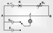
Standardization of Potentiometer: The process of determining potential gradient experimentally is known as standardization of potentiometer.
Let the balancing length for the standard emf E0 is l0 then by the principle of potentiometer E0 = xl0 ⇒ x = E0/l0
Sensitivity of potentiometer: A potentiometer is said to be more sensitive, if it measures a small potential difference more accurately.
(i) The sensitivity of potentiometer is assessed by its potential gradient. The sensitivity is inversely proportional to the potential gradient.
(ii) In order to increase the sensitivity of potentiometer
(a) The resistance in primary circuit will have to be decreased.
(b) The length of potentiometer wire will have to be increased so that the length may be measured more accuracy.
Difference between voltmeter and potentiometer
Voltmeter
Potentiometer
It's resistance is high but finite
It's resistance is infinite
It draws some current from source of emf
It does not draw any current from the source of unknown emf
The potential difference measured by it is lesser than the actual potential difference
The potential difference measured by it is equal to actual potential difference
Its sensitivity is low
Its sensitivity is high
It is a versatile instrument
It measures only emf or potential difference
It is based on deflection method
It is based on zero deflection method

Bulbs in series and parallel for CET aspirants


Combination of Bulbs

Bulbs in Series
(i) Total power consumed 1/Ptotal = 1/P1 + 1/P2 +...
(ii) If ‘n’ bulbs are identical, Ptotal = P/N

Bulbs in series
(iii) Pconsumed (Brightness) ∝ V ∝ R ∝ 1/Prated i.e. in series combination bulb of lesser wattage will give more bright light and p.d. appeared across it will be more.
Bulbs in Parallel
(i) Total power consumed
            Ptotal = P1 + P2 + P3 +...+ Pn
(ii) If ‘n’ identical bulbs are in parallel Ptotal = nP

Bulbs in parallel
(iii) Pconsumed (Brightness) ∝ PR ∝ i ∝ 1/R i.e. in parallel combination, bulb of greater wattage will give more bright light and more current will pass through it.
Solved example 1: An electric bulb is rated 220 volt and 100 watt. Power consumed by it when operated on 110 volt is
(A) 50 watt      (B) 75 watt      (C) 90 watt      (D) 25 watt
Solution: (D) Resistance of the bulb V2/PRotate = 220×220/100 = 484 Ω
When connected with 110 V, the power consumed
            Pconsumed = V2/R = 110×110/484 = 25W
Solved example 2: Two bulbs are working in parallel order. Bulb A is brighter than bulb B. If RAB are their resistance respectively then and R
(A) RA > RB                             (B) RA < RB
(C) RA = RB                             (D) None of these
Solution: (B) In parallel Pconsumed ∝ Brightness ∝ 1/R
PA > PB (given). RA < RB

Heating Effect of Electric Current


Heating Effect of Current

Joule Heat
When some potential difference V is applied across a resistance R then the work done by the electric field on charge q to flow through the circuit in time t will be  
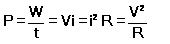
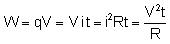
Joule. This work appears as thermal energy in the resistor.
Heat produced by the resistance R is  
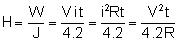
Cal. This relation is called joules heat.
Electric Power
The rate at which electrical energy is dissipated into other forms of energy is called electric power i.e.
Units: It’s S.I. unit is Joule/sec or Watt
Bigger S.I. units are KW, MW and HP, remember 1 HP = 746 Watt
Rating values
On electrical appliances (Bulbs, Heater, Geyser … etc). Wattage, voltage, … etc. are printed called rating values e.g. If suppose we have a bulb of 40 W, 220 V then rated power (PR) = 40 W while rated voltage (VR) = 220 V.
Resistance of electrical appliance
If variation of resistance with temperature is neglected then resistance of any electrical appliance can be calculated by rated power and rated voltage i.e. by using 
Power consumed (illumination)
An electrical appliance (Bulb, heater, … etc.) consume rated power (PR) only if applied voltage (VA) is equal to rated voltage (VR) i.e. If VA = VR
So Pconsumed = PR. If VA < VR then Pconsumed = VzA/R also we have R = VzR/PR
So Pconsumed (Brightness) = (V2a/V2R) × PR
Long distance power transmission
When power is transmitted through a power line of resistance R, power-loss will be i2R
Now if the power P is transmitted at voltage V then P = Vi , i.e. i = (P / V)
So Power loss = P2/V2 × R
Now as for a given power and line, P and R are constant so Power loss ∝ (1/V2)
So if power is transmitted at high voltage, power loss will be small and vice-versa. This is why long distance power transmission is carried out at high voltage.
Electricity Consumption
1. The price of electricity consumed is calculated on the basis of electrical energy and not on the basis of electrical power.
2. The unit Joule for energy is very small hence a big practical unit is considered known as kilowatt hour (KWH) or board of trade unit (B.T.U.) or simple unit.
3. 1 KWH or 1 units is the quantity of electrical energy which dissipates in one hour in an electrical circuit when the electrical power in the circuit is 1 KW thus 1KWH = 1000W × 3600 sec = 3.6 × 10⁶ J.
4. Important formulae to calculate the no. of consumed units is
        n = Total Watt × Total Hours/1000
Solved example 1: Two heater wires of equal length are first connected in series and then in parallel. The ratio of heat produced in the two cases is
(A) 2 : 1       (B) 1 : 2         (C) 4 : 1                 (D) 1 : 4
Solution: (D) Power consumed means heat produced.
For constant potential difference Pconsumed = Heat ∝ 1/Req
H1/Hz = Rz/R1 = R/2/2R = 1/4       (Since Rz = R.R./R+R = R/2 and R1 = R + R = 2R)
Solved example 2: A wire when connected to 220 V mains supply has power dissipation P1. Now the wire is cut into two equal pieces which are connected in parallel to the same supply. Power dissipation in this case is P2. Then P2 : P1 is
(A) 1            (B) 4              (C) 2                      (D) 3
Solution: (B) When wire is cut into two equal parts then power dissipated by each part is 2P1
So their parallel combination will dissipate power
P2 = 2P1 + 2P1 = 4P1, Which gives P2/P1 = 4.

Question of the day


    A magnetic needle lying parallel to a magnetic field requires W units of work to turn it through 60°. The torque needed to maintain the needle in this position will be
            (A) Ö3 W                                                          (B) W
            (C) (Ö3/2) W                                                    (D) 2W


Share

Twitter Delicious Facebook Digg Stumbleupon Favorites More